Development of custom electronic boards with CNC Router.
Testing design rules for 3D printers is essential to validate and optimize designs before final printing. These tests help identify potential problems, reduce errors and costs, improve the efficiency of the printing process, and facilitate continuous learning in designing for 3D printing. In short, they are essential to guarantee quality, precision and efficiency throughout the 3D printing process.
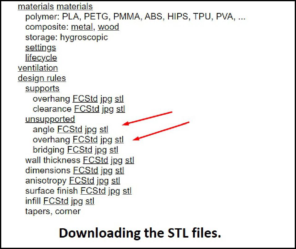
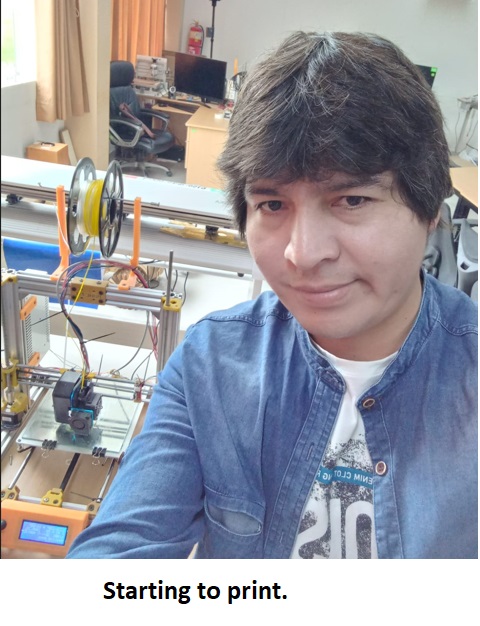
With enthusiasm, our team decided to get to work, or rather, machines to work! We all set about printing the downloaded STL files. Personally, I decided to put the 3D printer I built at home in Huánuco Peru to the test. It is exciting to see our creations take physical form through this printing process.
Bridging printing with PLA
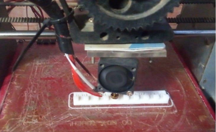
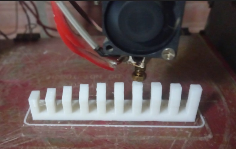
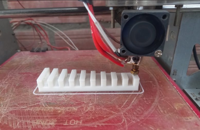
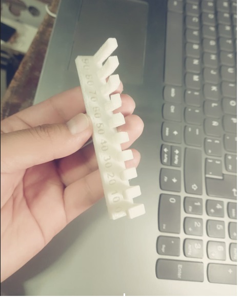
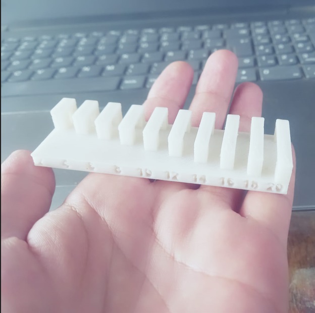
Angle printing with PLA
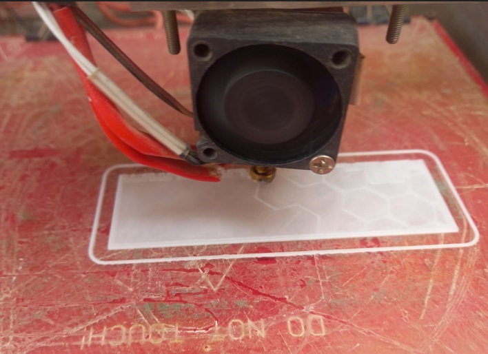
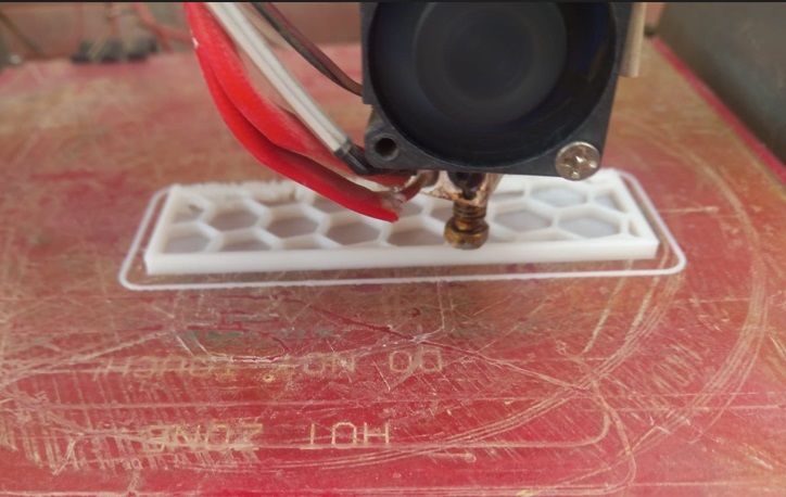
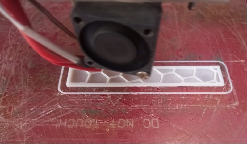
The following images show examples of bridging and angle printed with PLA material using the 3D printer I built.
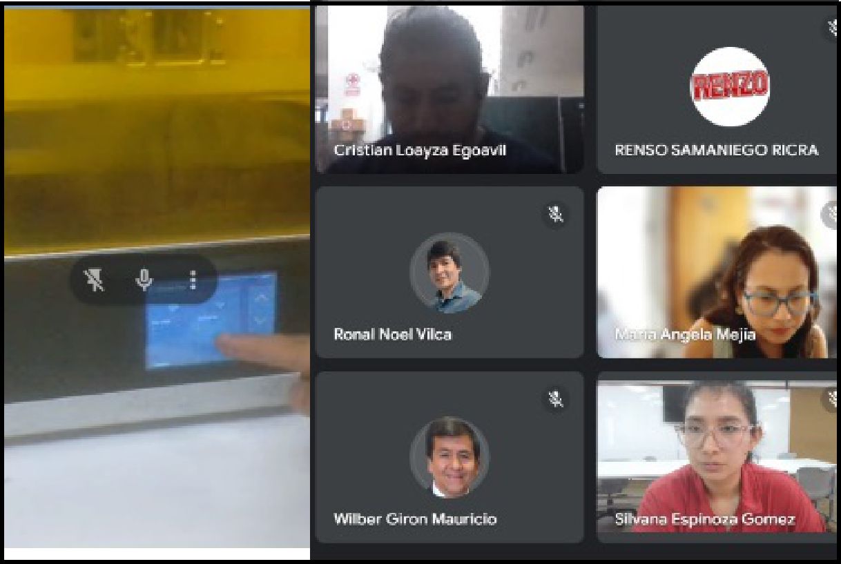
The file was shared among the entire team to ensure that everyone has access to the prints made on the different machines.

Once the prints were finished, we decided to collect all the files in a shared folder. In this folder, we gather all the prints made on the different machines by our team. This action allows us to have an organized and accessible record of our collaborative work.
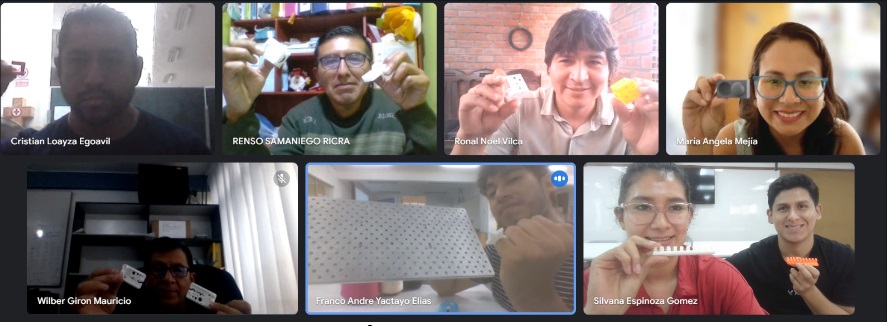
Group work meeting
3D scanning and printing technology refers to the process of creating three-dimensional physical models from digital data. 3D scanning involves capturing the shape and geometry of a real-world object using specialized devices, such as laser scanners or 3D cameras. These devices collect information about the surface of the object by emitting light or laser, and then process that data to create a 3D digital model.
Once a digital model has been generated, either with the 3D Scanner or your own design in some 3D design software, a 3D printer can be used to physically manufacture the object. 3D printers work by depositing successive layers of material, such as plastic, metal or resin, to build the object layer by layer, following the instructions of the digital model. This process allows for the rapid and accurate creation of prototypes, custom parts, and a variety of other products.
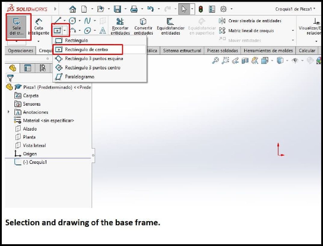
To design this particular solid, use Solidworks software and perform the following steps:
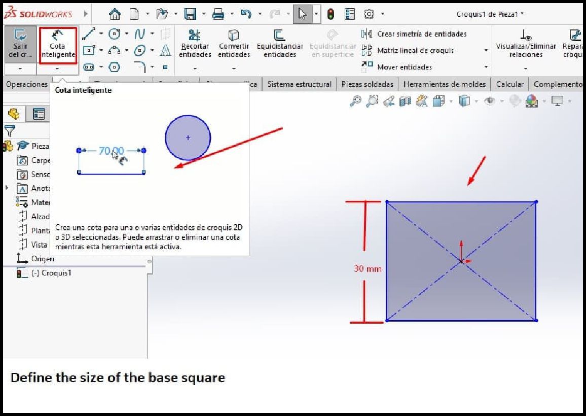
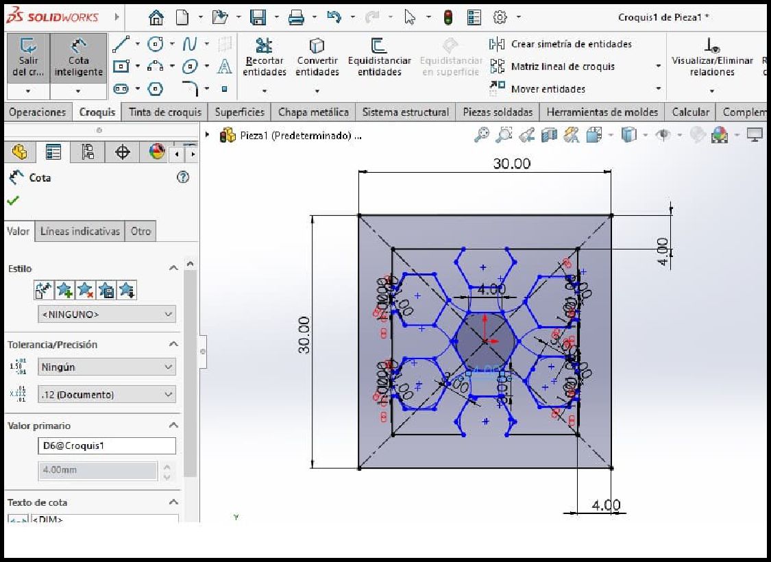
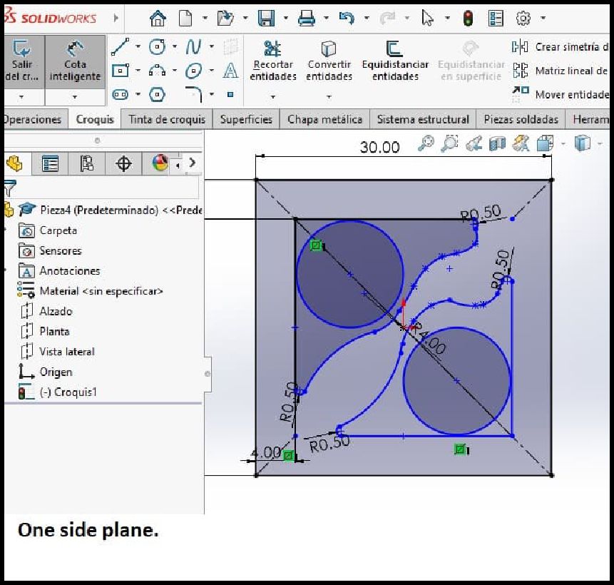
To get started, open the Solidworks environment and access the sketch section. Next, choose the plane where you want to draw the solid. Next, select the desired shape for your solid from the toolbar. In my case, I went with a square, since I'm designing a cube. Without forgetting to place the desired size, for this we select the smart dimension tool and then on one of the sides of the square.
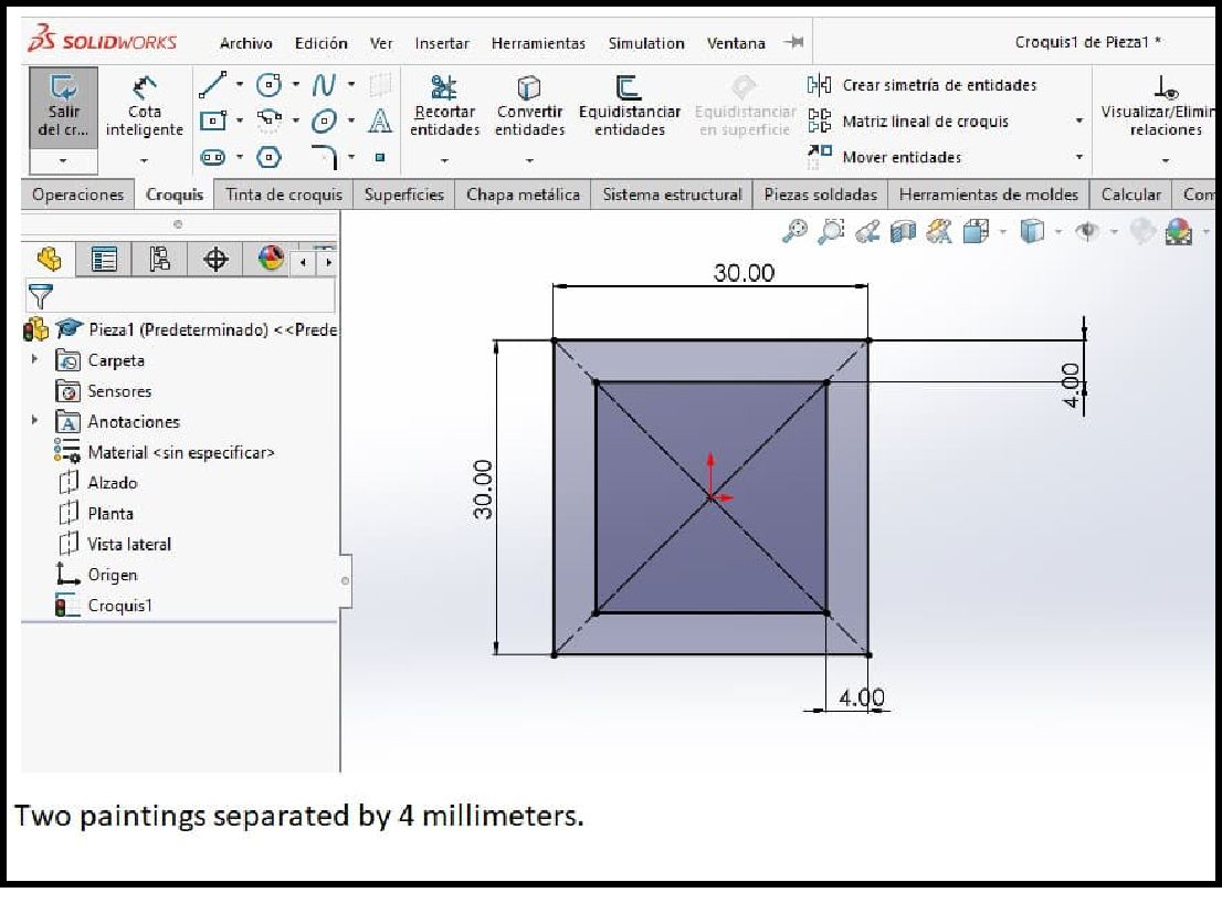
Next, we create a second inner square that will be separated from the outside by 4 millimeters, keeping the outer edge 30 millimeters. Additionally, we can incorporate more interior designs to achieve the specific shape desired for our solid.
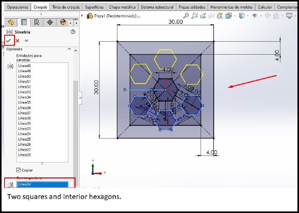
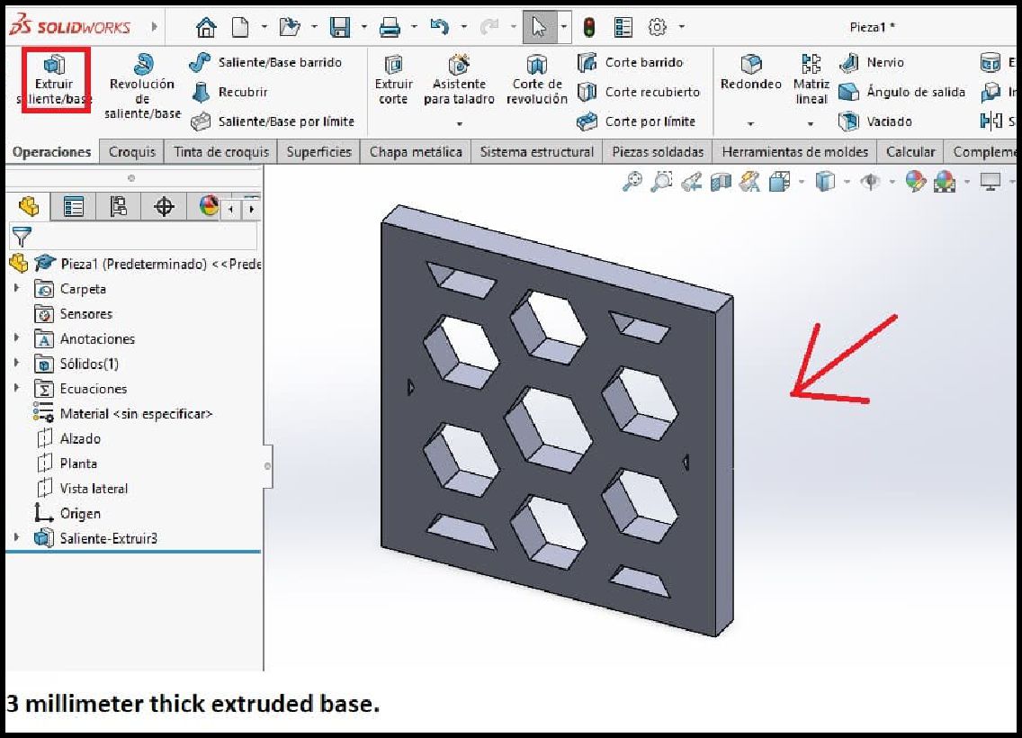
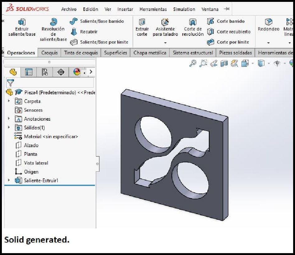
The next step is to standardize the final design of one face of the cube to later extrude it with the desired shape, making sure that it has a thickness of 3 mm.
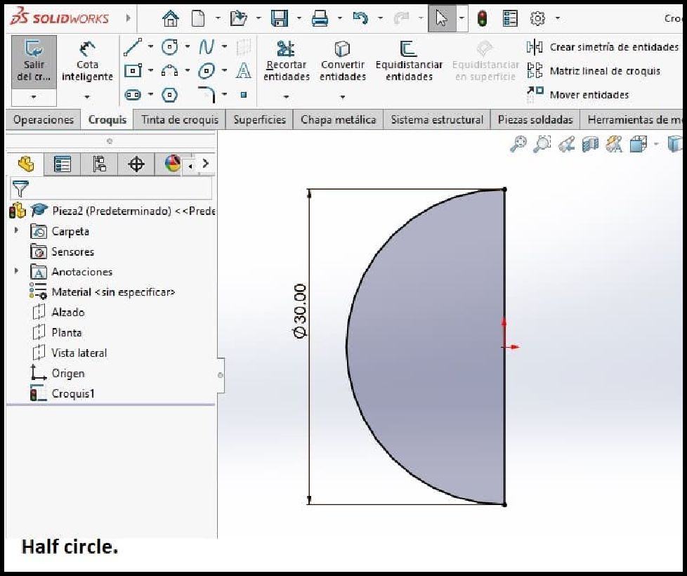
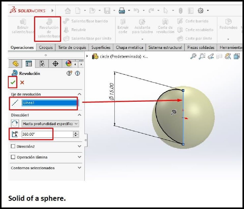
The next step involves creating a sphere-shaped solid. To do this, we begin by drawing a half circle and then use the "smart dimension" tool to establish its dimensions, setting a radius of 15 millimeters. Once we have adjusted the measurement correctly, we proceed to use the revolution operation. This operation requires that we select the line that we want to use as the axis of revolution, which in this case would be the vertical axis (the diameter of the circle), and as a reference. The result of this operation will be a sphere.
The attached image shows the design of another face that will be part of the cube that will be assembled in the end.
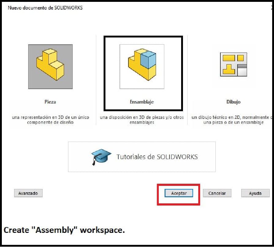
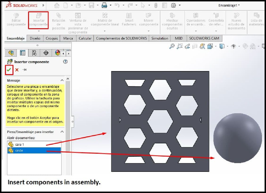
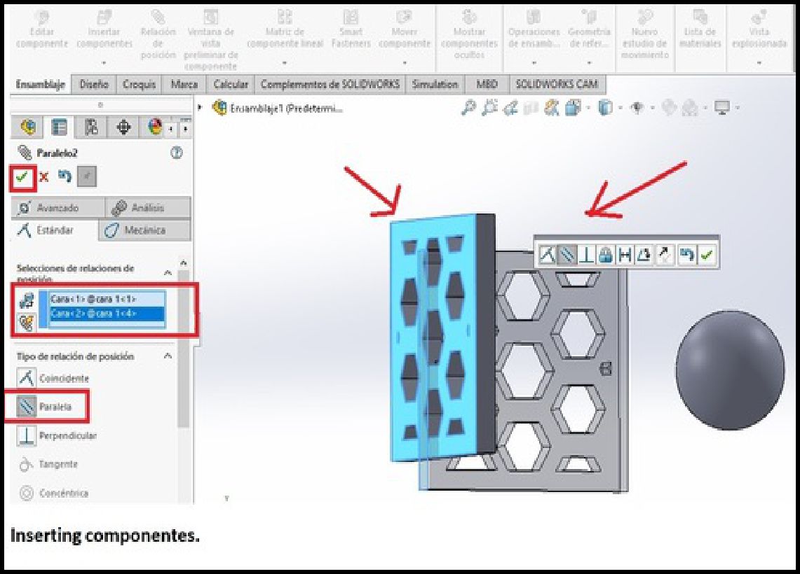
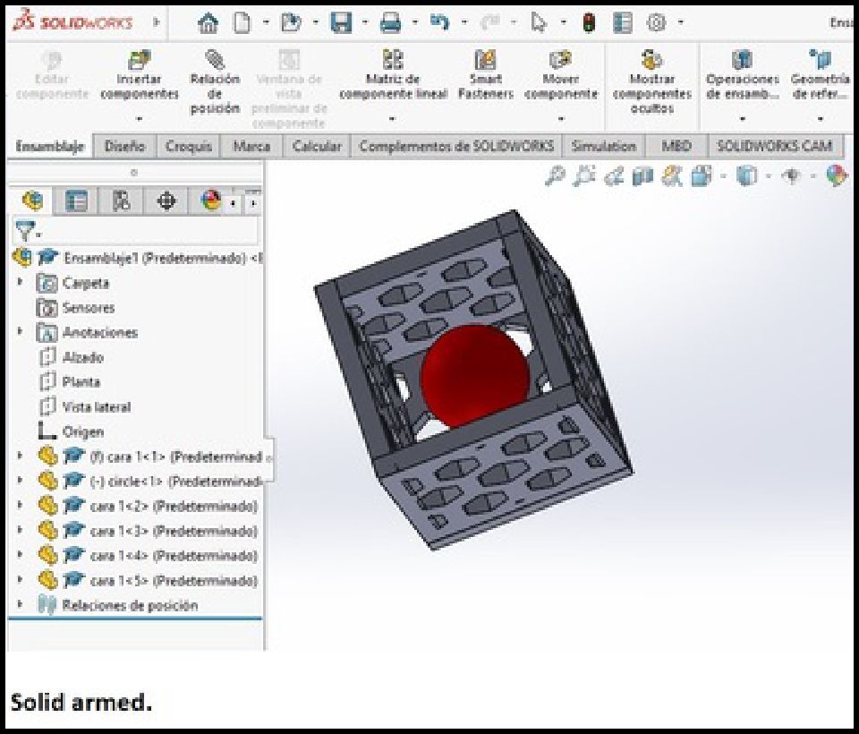
Next, we proceed to configure an assembly sheet environment in Solidworks, as illustrated in the corresponding figure. Then, we insert all the previously created solids, including the faces to form the cube and the sphere that will be located inside it.
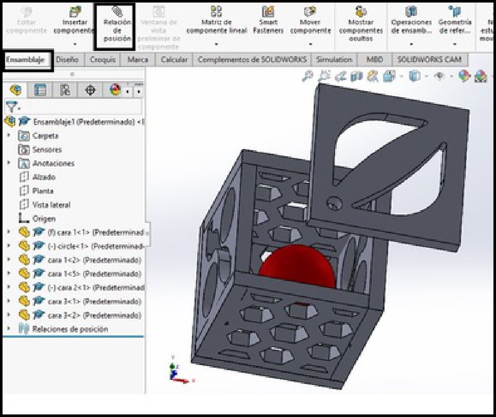
The next step involves joining the components to form the structure of a cube, making sure to consider the positional relationship between each piece. To do this, we select the "Mate" tool and choose from the available options, such as faces, edges or vertices. Through this tool, we establish relationships such as perpendicularity, tangency, parallelism or coincidence, as shown in the attached image.
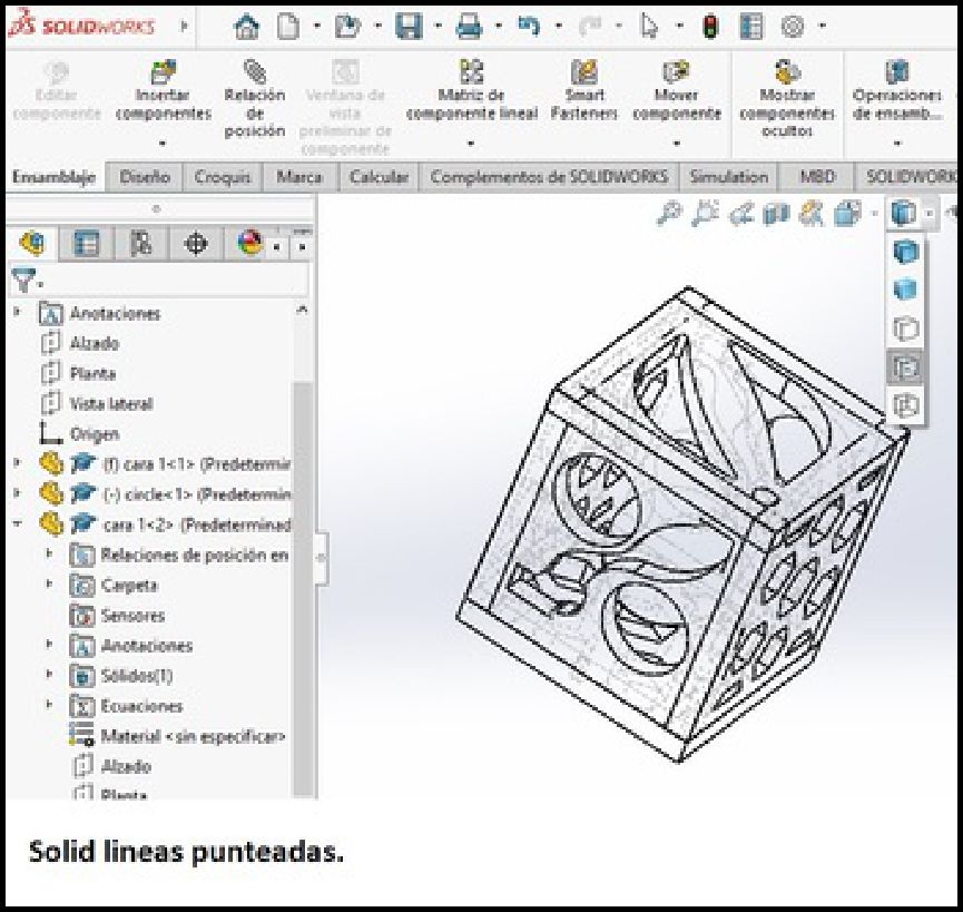
The following image represents the final assembly process of the isometric figure, where the last step of joining and concluding the entire cube is observed.
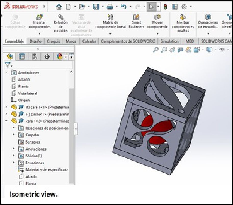
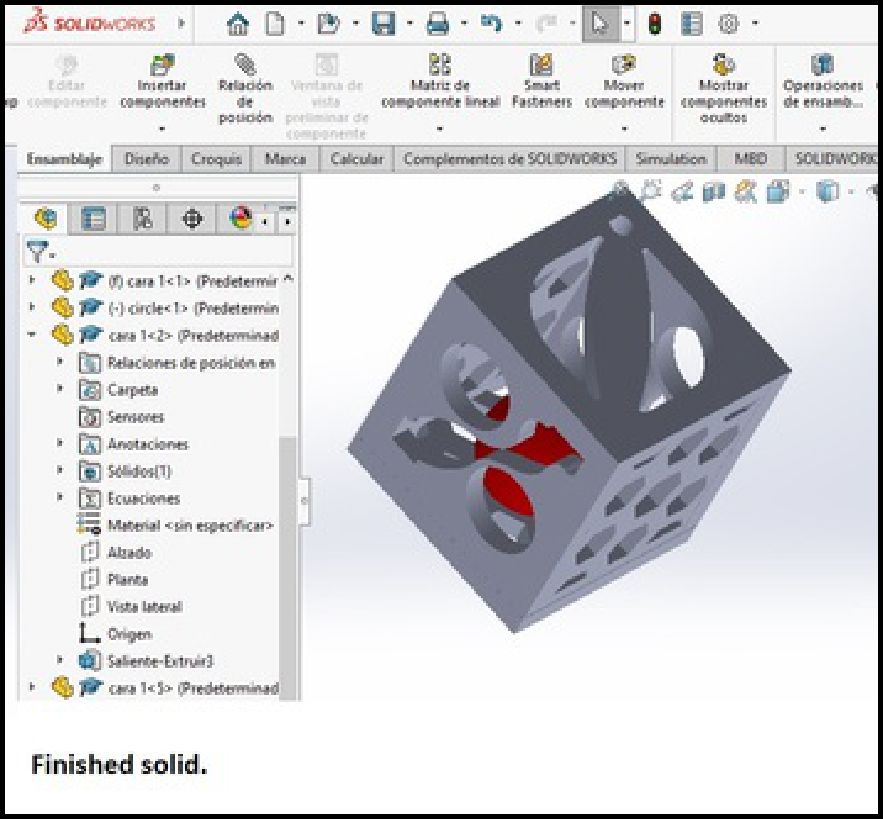
The first image shows the isometric figure with all construction lines visible, while the next image shows the isometric solid as it should look after 3D printing.
o conclude this process, it is necessary to export it in STL format and then perform G-code generation. For this stage, we can view it in the 3D Builder software and later import it to the Prusa Slicer.

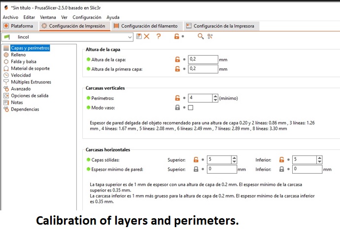
For the printing phase, we begin by opening the Repetier Host software and proceed to import the previously created solid model. Next, we go to the SLICER module, it will immediately display 3 options Slicer, Cura and Prusa Slicer. In my case I will use the Prusa Slicer, where we will configure all the relevant printing parameters, such as the thickness of the layers and the perimeter, the padding , the generation of skirts, the need for supports, the printing speed, among other fundamental aspects.
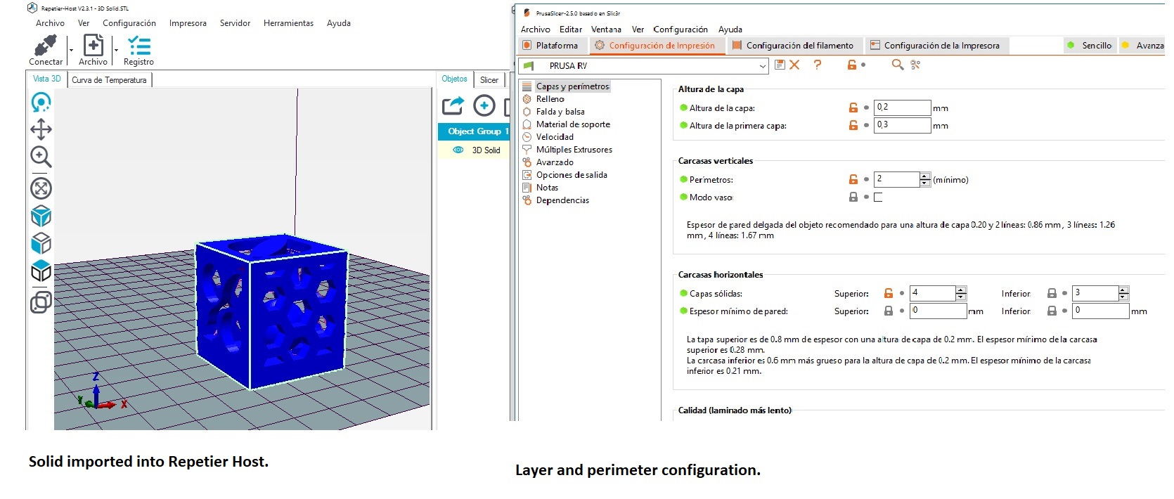
In the previous image, you can see the configuration of the layers and perimeters. This setting refers to the height that each layer of the solid will have. The smaller the layers, the higher the resolution and smoothness of the final product. However, this will also mean longer printing time and higher material consumption. Another aspect to take into account is the height of the first layer, which determines the initial solidity of the object. Additionally, it is crucial to set up solid layers; At this point, it is established how frequently the solid will be completely filled. In our case, it has been set in every four layers.
When the number of solid layers in the print is increased, the resulting part tends to be stronger and more consistent, as each layer contributes to the structural integrity of the object. However, this approach entails greater material consumption. On the other hand, there is the option to print without padding, simply setting the value to zero. This will result in a lighter product and reduced printing time, as well as less material waste.
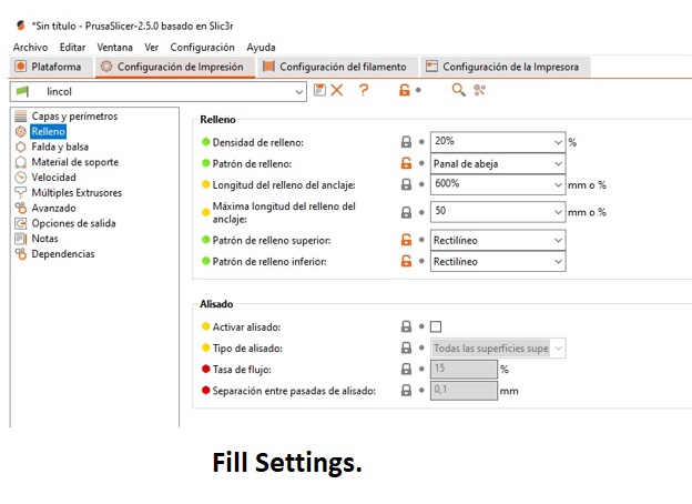
This section specifies the type and percentage of infill that the printing machine will use. In my case, I have selected 20% infill, as the printed object will not be exposed to significant forces or pressures and will be used primarily for testing purposes. Additionally, I have opted for the type of filling known as "honeycomb", which has proven to be one of the most efficient and consistent structures according to previous studies.
As for the top fill pattern, I have chosen the "Rectilinear" type, which is applied on each solid fill layer. This pattern offers a uniform distribution of the material, contributing to the stability and resistance of the printed object.
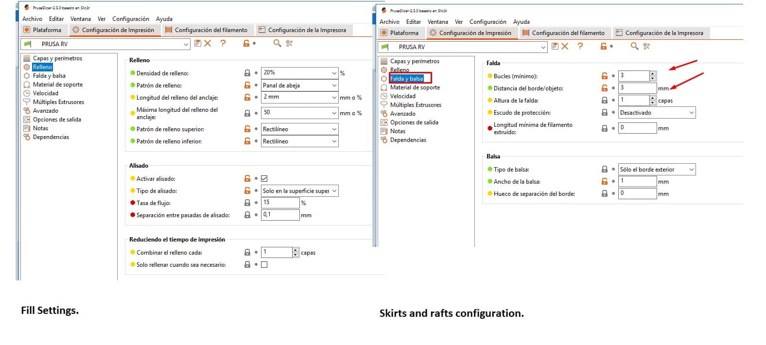
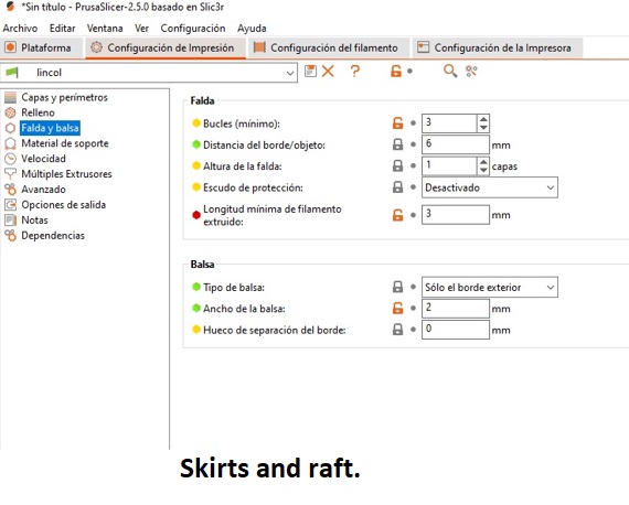
he Skirts and Rafts configuration determines the printing of a certain number of layers, the number of times it is repeated, and the distance it is placed from the solid object. In my case, I have established a single layer, separated from the solid by 3 millimeters and repeated three times. This setting is intended to clean the nozzle and check if the hot bed is level before starting printing the main object.
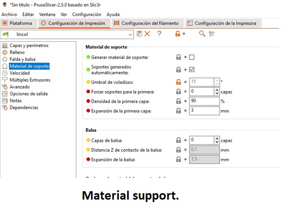
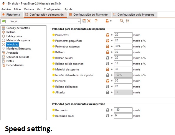
As for the material supports, they are enabled for those cases in which the solid requires support to obtain better results, especially when the angle of inclination of the object to be printed reaches 45°. In addition to activating this function, the distance between the supports and the material is configured, setting it to 0.2 mm in my particular case. Selecting the right type of support fill is crucial; In my case, I have opted for the "rectilinear" filling to facilitate its extraction without making it too rigid. As for printing speeds, these are adjusted depending on the level of detail of the design and the size of the object. It is important to find a balance, as very high speeds can compromise design details. Various speeds are configured, such as fill speed, outer and inner layer speeds, among others, to optimize the printing process and ensure accurate results.

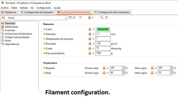
At this point, it is crucial to adjust the diameter of the filament, which in my case is 1.75mm, however, I have had better results by modifying it slightly to 1.8mm. This alteration appears to fool the machine, resulting in more effective material deposition.
Another vital aspect is the temperature of the extruder. Initially, I set it at 210 degrees to ensure good adhesion of the material to the hot bed. After the first layer, I reduce the temperature to 208 degrees, as this is the optimal melting temperature for PLA.
As for the hot bed temperature, I start with 60 degrees for better initial adhesion of the material, but then lower it to 55 degrees. This change is necessary to prevent material lifting or corner warping during subsequent layers.

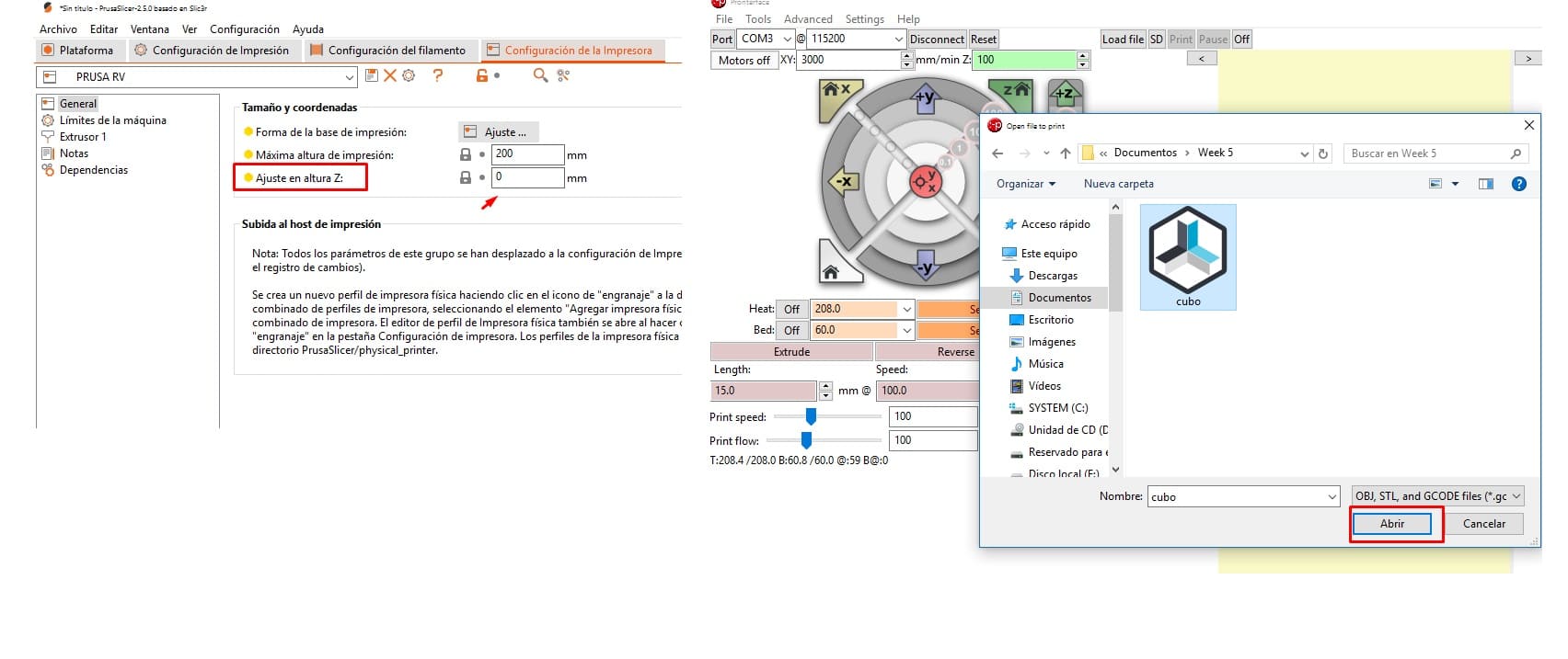
After configuring the printing parameters, the next step is to save the generated Gcode file to a Micro SD card or a folder on your computer. Once this is done, open the Pronterface executable to view the printing process. From the Pronterface interface, select the appropriate serial port and the baud rate, which in my case is 115200. Then, we connect the printer to the program.
 Once the printer is connected, you can make adjustments to the X, Y, and Z axis movements if necessary, as well as control the extruder temperature and hot bed temperature. Next, import the generated Gcode file from the source folder using the Pronterface interface and click the print button to start the printing process.
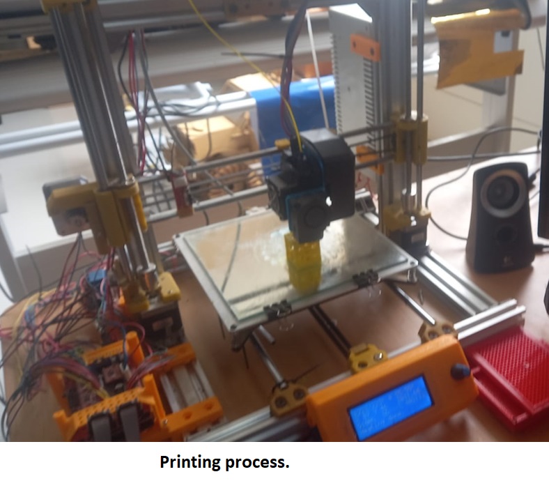
The image below illustrates the entire printing process necessary to obtain our solid 3D cube. As can be seen in the images, a sequence is presented in which the first step involves printing the first layer. Furthermore, at a separation of 3mm, a square contour known as skirts is observed. In my case it consists of 2 lines that are printed before starting the object. These skirts are sufficient to clean the nozzle and ensure a smooth start throughout the printing process.
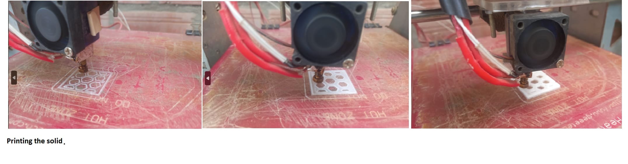
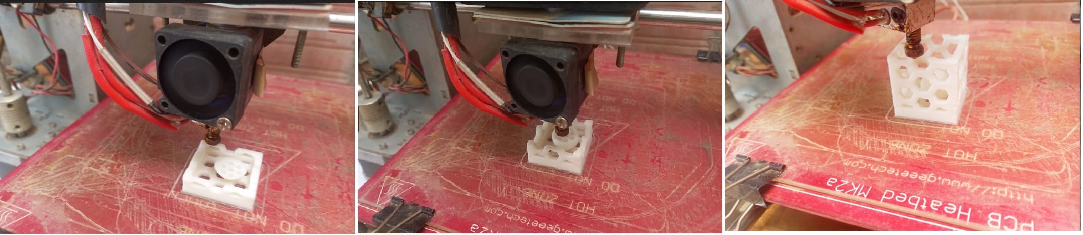
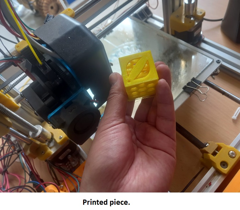
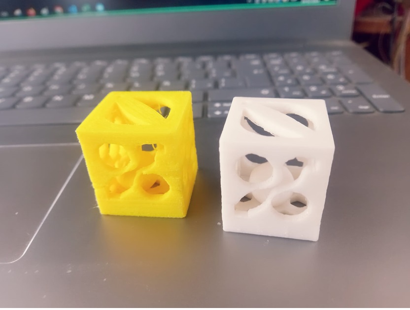
The result is a cube with faces of different designs, inside there is a sphere, as can be clearly seen in the figure.

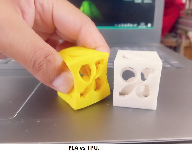
As I mentioned at the beginning of the assigned tasks, I will use the printer that was built in the FABLAB UNHEVAL of the National University Hermilio Valdizán, under my advice. This printer will be used for printing with TPU material, with the aim of exploring the particularities that this material presents.
In the PrusaSlicer software, we set the height of each layer. We understand that the lower the layer height, the better the resolution of the printed piece, although this also leads to greater material consumption and an increase in printing time. Another important point to consider is solid layers; in my case I set them to 5, which means a full fill is done every few layers.
Another crucial aspect is the percentage of infill that our 3D piece will have, in my case, I have set it to 20%. Furthermore, I have selected the "honeycomb" type of filling, while the filling of the solid parts is rectilinear. It is important to note that as the infill percentage increases, both printing time and material consumption also increase.
As for the skirts, I left them configured as in the previous case, using PLA. As for the supports, I also chose not to activate them, since I am working with TPU. Removing material or supports could damage the printout, as shown below.
Finally, configure the speed as indicated in the image. As you can see, a low speed has been set due to the use of TPU, as well as the presence of an interior object that cannot be extracted. Another important aspect is the temperature setting: the extruder has been set to 220°C, while the hot bed is at 60°C for the first layer and 55°C for the following layers.
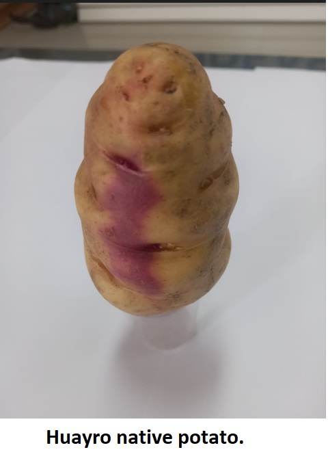
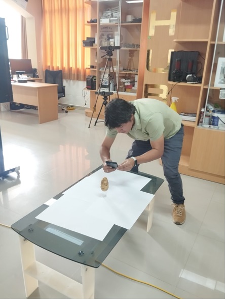
To perform the scan, a cell phone is used to take high-quality "48K" photographs and the KIRI Engine mobile application. It is important to ensure that the background is white to prevent other objects from being scanned. In this case, a sample of one of the native potatoes from central Peru will be selected, specifically from the Huánuco region. This region is known for hosting a wide diversity of potatoes, with around 360 registered varieties, while throughout Peru it is estimated that there are more than 4,000 varieties in total. A great challenge to scan and catalog all these varieties for their exhibition at MINCUL - Peru. In the context of our task, we will focus on scanning the 'HUAYRO' potato.

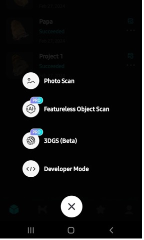
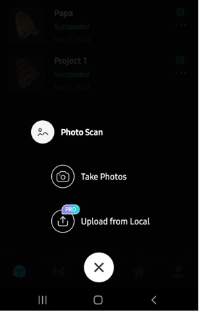
To start the scanning process, we open the KIRI Engine application. We are given the option to choose between video or photo scanning. In my case, I opt for scanning with photos. Then, the system asks us if we want to carry out the process automatically or manually. At this point, we select the corresponding option. During scanning, a total of 70 photographs of the object are captured from different angles to ensure a complete representation.
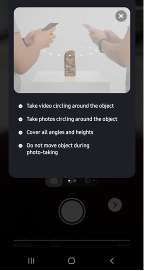
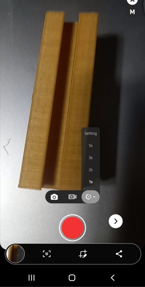
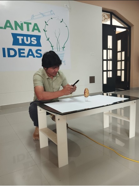
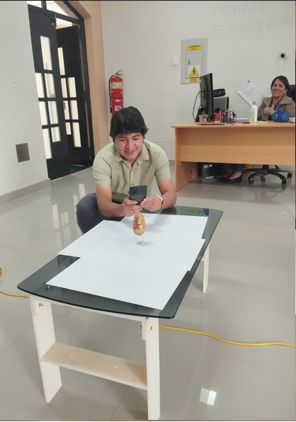
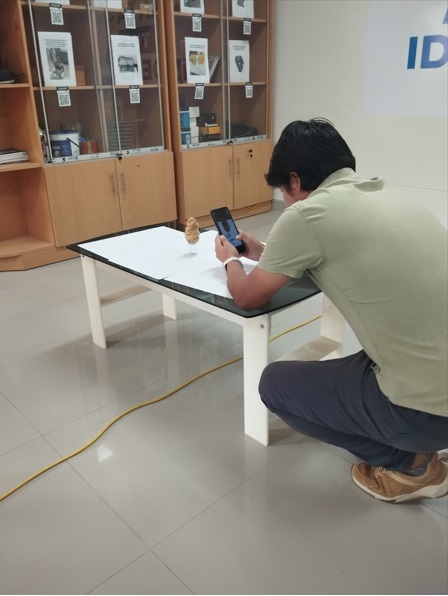
The scanning process requires time and patience, as it involves taking photographs continuously without losing the rotation angle. It is essential to capture images from all angles to obtain a 360-degree view of the object. Additionally, it is important that the object be placed on a white surface for proper contrast. In my case, I chose to place the potato on a transparent glass positioned on a white paper base, all on a coffee table. This arrangement helps maintain the stability of the object and makes it easier to capture images from different perspectives.
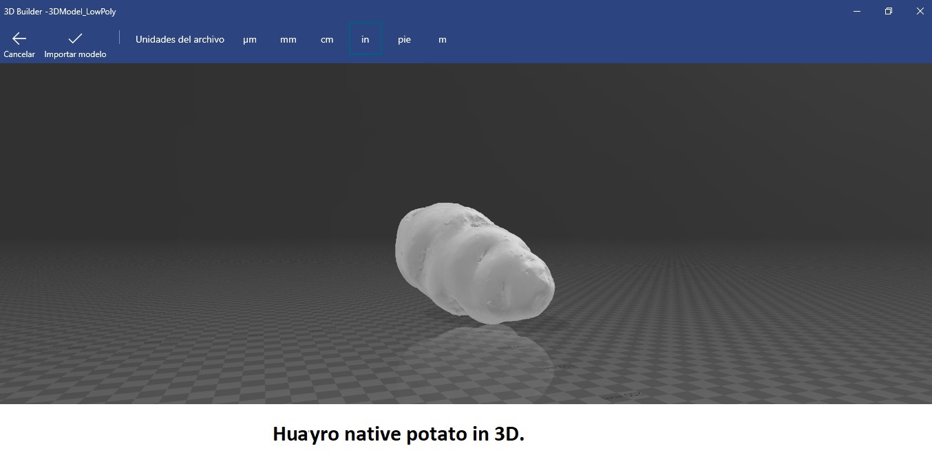
Subsequently, the application automatically processes the 70 captured photographs. This automatic processing process usually takes around 20 minutes. Once completed, the scanned product is ready for use. In my case, the scanned product corresponds to the native potato 'Huayro'.
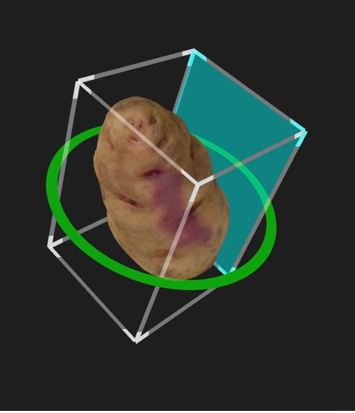
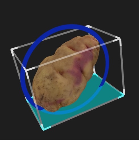
3D view of the scanned potato
Finally, we export the file to STL format. With this, we have completed the scanning process and now have available the digital representation of one of the 4000 varieties of potatoes native to Peru. This file is ready to be used in 3D printing with the corresponding printer.
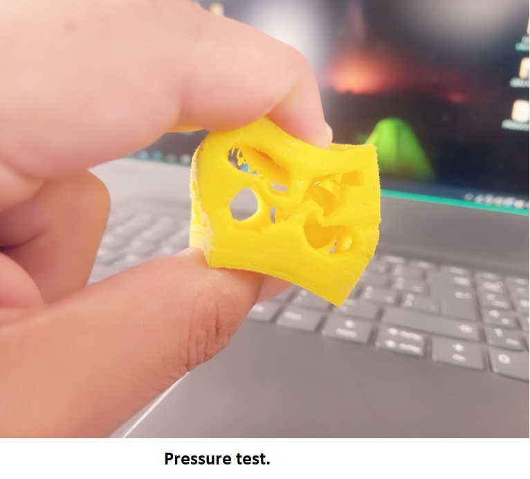
The experience gathered in this task highlights the challenges of working with one solid within another. For this challenge I worked with PLA, the parameters have to be calibrated very well and especially when TPU is used, I also put it to the test due to its flexibility. In addition, the importance of accurate machine calibration is highlighted, especially in the Z axis, since poor calibration can damage it. It is essential to remember not to touch the extruder, which reaches temperatures above 200°C, and to stay away from the printer while it is in operation. In conclusion, it is recognized that each part and material requires its own calibration and you have to know the machine well and the calibration parameters are essential to obtain fine parts with a good finish.
También hemos aprendido que las impresoras 3D son herramientas muy útiles para la creación de piezas únicas a bajo costo de producción. Desde una perspectiva industrial, esto nos permite realizar prototipos de nuevos productos a un costo reducido y facilita la iteración en el diseño. Es importante tener en cuenta que, debido a que generalmente se utilizan materiales blandos en la impresión 3D, los productos resultantes suelen ser prototipos. Sin embargo, este proceso es invaluable para la creación y mejora de prototipos antes de la producción en masa.
Before starting this task, I would like to show you the homemade 3D printer that I will be using for my activities this week.
I would like to share a summary of my experiences with my 3D printer. At first, I decided to use ABS filament because of its resistance. However, I encountered difficulties when working with this material due to the strong odor and toxicity of the gases it emits. Furthermore, even small air currents caused distortions in the print. As a solution, I realized the need for the machine to be airtight to address these issues. For this reason, I opted for PLA and decided to stick with this material. PLA has a cheaper price, adapts better to the environment and does not require a closed environment for printing.
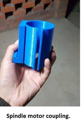
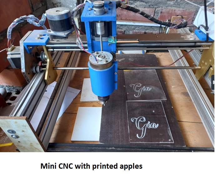
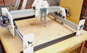
The image below shows how I used my 3D printer to make the Spindle motor coupling. I also built a mini CNC thanks to the 3D printer, whose X, Y and Z axis couplings are made of PLA material. Without the help of the 3D printer, it would have been difficult to create these components.
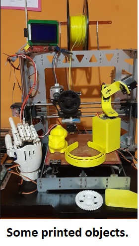
I carried out several calibrations and little by little I managed to set the parameters of my 3D printer as mentioned in the assigned personal task. In the image below, I present some printed objects, including a robotic hand, a camera stabilizer, gears, and a headband designed for a Covid face protection mask.

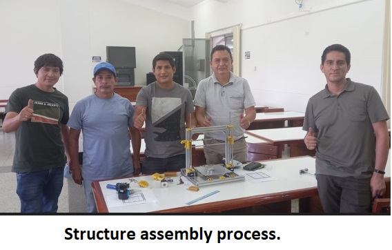
With the help of my printer, I was able to build more printers, since I made the prints of the couplings and joints for future 3D printers. These components were used in a course I taught called "Build Your 3D Printer". With my advice and supervision, the participants advanced with enthusiasm during the course, which lasted approximately one month, focused on continuous practice.
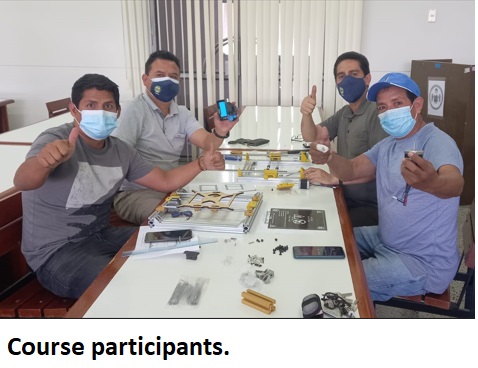
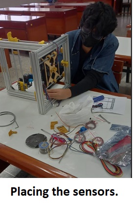
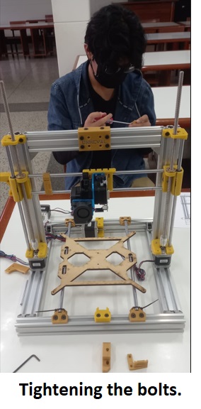
It was quite a challenge for the participants, since it was their first experience in assembling this type of machines, but they tackled it excellently.
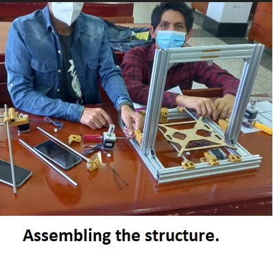
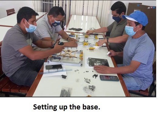
They managed to put the machine together, although they had doubts at first, but once they immersed themselves in the course, everything flowed naturally, applying the Lego-like construction principle.
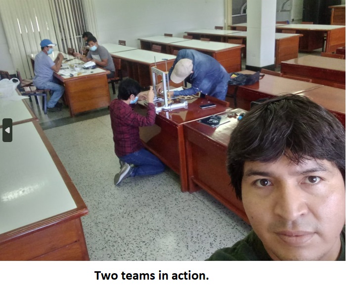
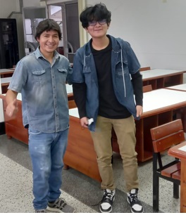
It was an unforgettable experience to work with brave and committed people, who give their best to achieve their goals.
1. Side 1.
2. Side 2.
3. Side 3.
4. Sphere.
5. 3D Solid.
6. Original solid.
5. Potato Huayro.
Development of custom electronic boards with CNC Router.
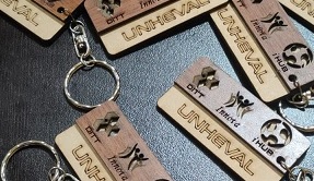
Development of personalized keychains and ornaments with CNC Laser.
Development of custom machines "Desktop CNC Laser.

Huánuco is a Peruvian city, capital of the district, province and department of the same name in the north-central area of the country. The city has a population of 235,529 inhabitants. .